

High-speed integrated rope device is a simple rope device with high performance latest developed by SINSIM, aiming to improve the rope embroidery efficiency and quality. At present, the existing simple rope embroidery in the market is low in stability, easy to go around the rope and throw the step and so on. The highest speed is 800rpm with low efficiency.The new product will be equipped with the encoder of the ring motor and the closed-loop control, the maximum embroidery speed can reach up to 1200rpm without slow speed, and the efficiency is increased by nearly 50%. And because of the closed loop control, the system consumes much less energy than the open loop system. Even at the maximum speed of 1200 RPM, the motor will not be hot and the reliability will be greatly improved.
High efficiency. It can be increased from 800rpm to 1200rpm and increased efficiency by 50%
Embroidering is good. The motor speed is fast. The shorter time reaches the specified position, avoiding the leakage needle
There is no needle missing. The loop motor is controlled by encoder, and the closed-loop control is used to avoid the inherent shortcomings of the open-loop throw.
Installation is simple. Integrated model installation, and the line does not wear large beams, which saves time and money.
Low power consumption, low heat. With closed loop motor control, the current is 50% less than open loop and the ring motor is not more than 10 degrees.
Zero position accuracy, adopt the photoelectric encoder zero control, positioning error not exceed +-4 pulse
The self-check aging mode can be used to check the power of the plug and motor failure.
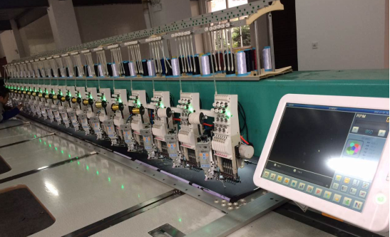
M98 installation effect of a whole rope embroidery machine
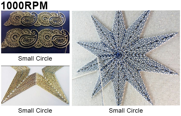
1.4 Model specification
At present, the two devices are shown in the picture. The customers can choose according to self requirements.
The mechanical installation dimensions are basically the same. Each rope embroidery device has the right or left type.
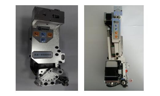
Model description
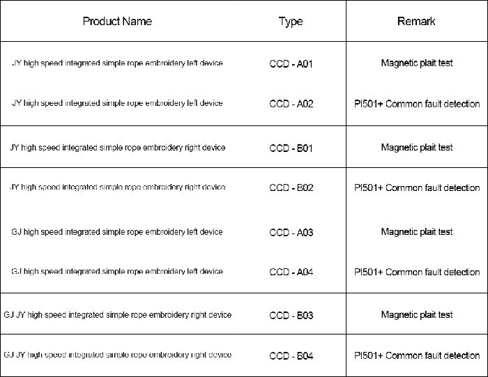
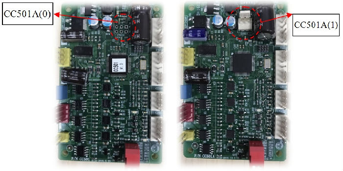
As is shown above, left is CZ014 without 3P and the socket is CC501(0), cooperated with the magnetic braiding inspection; right is CZ014 with 3P and the socket is CC501(0), mainly cooperated with PI501.
2.1 Board DIP setting
The DIP switch on board can be used for function selection. The installation has been set and the user does not need to set it. DIP1 represents the left and right devices, the default status (OFF) is the right device, and the left device is set to ON. DIP2 is used for self-test on board, and the default is OFF, which belongs to normal working condition. When dial ON, the ring will automatically enter the self-detection mode. If the normal aging mode is detected automatically, it will report an error.
2.2 Current state
Turn CZ019's 6 feet 24v power supply, 5 feet to the ground, connect to the power supply, and then turn on the power switch; After a second, the red light goes out and the green light flashes. At the same time, because the CPU detects the position of the swing pole, it will drive the wire motor to rotate according to the position of the swing pole. Rotate certain winding number to stop automatically, at this time the red light is not bright, the green light flashing. The delivery motor and ring motor are stopped.
2.2 Button instruction
The right light is a failure lamp. It has hardware failure when is always on. The fault code is displayed on the main control interface, and it is necessary to find out the cause of the failure. The red light flashing indicates that the rope breaks down, and the pull rod can continue to be embroidered. The green light means running the light, and the slow flash means the system is running. Flash indicates that the ring is turning and the lamp is out when it fails.
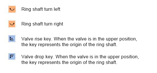
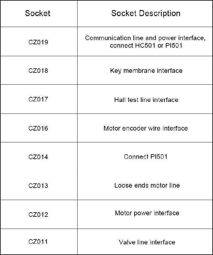
2.5 Pendulum lever operation instruction
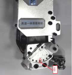
The pendulum mechanism is shown below. The position of the swing rod is tested by Hall. Loose line motor will move according to the position of pendulum lever. When the swing rod is tightened by the rope, the loose wire will give the line. When the swing rod is ejected by the spring, the loose wire will receive the line. The motor does not move in the middle position. The running frequency of the loose line motor can be set in the main control interface (1 ~ 15khz).
When high-speed simple rope embroidery control board (CC501) appears failure, it should be repaired the corresponding part and carry out corresponding operation.
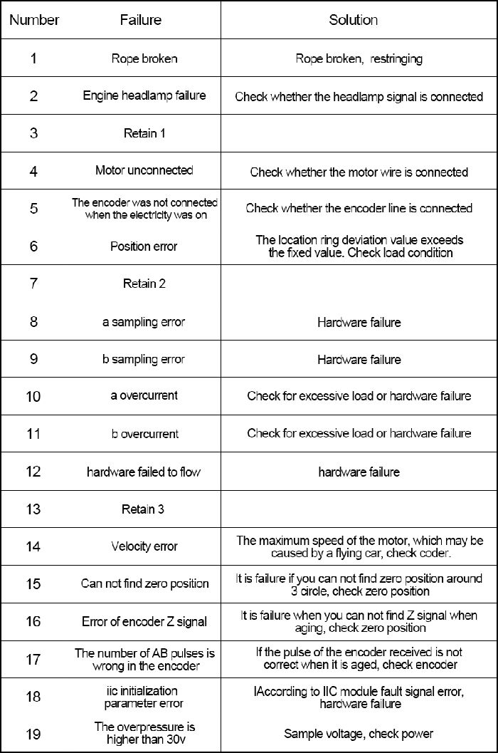
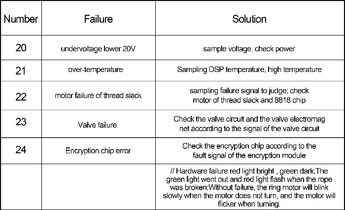
Chapter 4 Installation instructions
1. CC501 wiring diagram:

2.When the CC501 is connected to the HC501, the wiring diagram is shown below:

3. When CC501 is used with PI501, the wiring diagram is shown below

Note that the motor line will loosen the plug when installed. So on the device, the motor line is fastened to the following left image: If there is a loose need to be repressed.
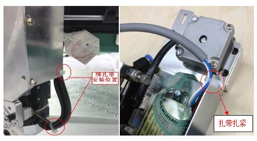
The machine head will move together with device when changing color. The connective line of the machine head and the device will also be loose. It also needs to be tied to the device during installation. As shown in the right image:
When CC501 is used with PI501, the attachment will pass through the girder. All cords should be fastened with a bandage to prevent the plug from loosening.